WIP - PAGE/PROJECT IN THE WORKS - WIP
I've come across more than a couple of occassions recently in which I found myself wanting to controllably spin stuff while tinkering on projects. The best tool at my disposal for this task was my "little" 6 inch rotary table for my mill.

While it's certainly up to the task, it's a heavy little bastard! So to keep me from lugging it up and down the stairs from the shop to the 'lab', I decided I should take a stab at a DIY, lighter-duty variant.
OnShape CAD files available to do with as you please here.
I have since moved this project over to Fusion. Only significant difference is the addition of a stepper mount and coupler.
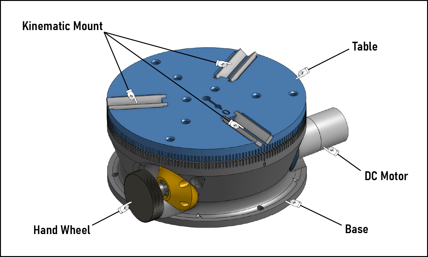
The above image shows the major externally-visible components. The Base is a printed part that provides not only the structural support for loads from all of the other components, but also is responsible for controlling the alignments of the motion components.
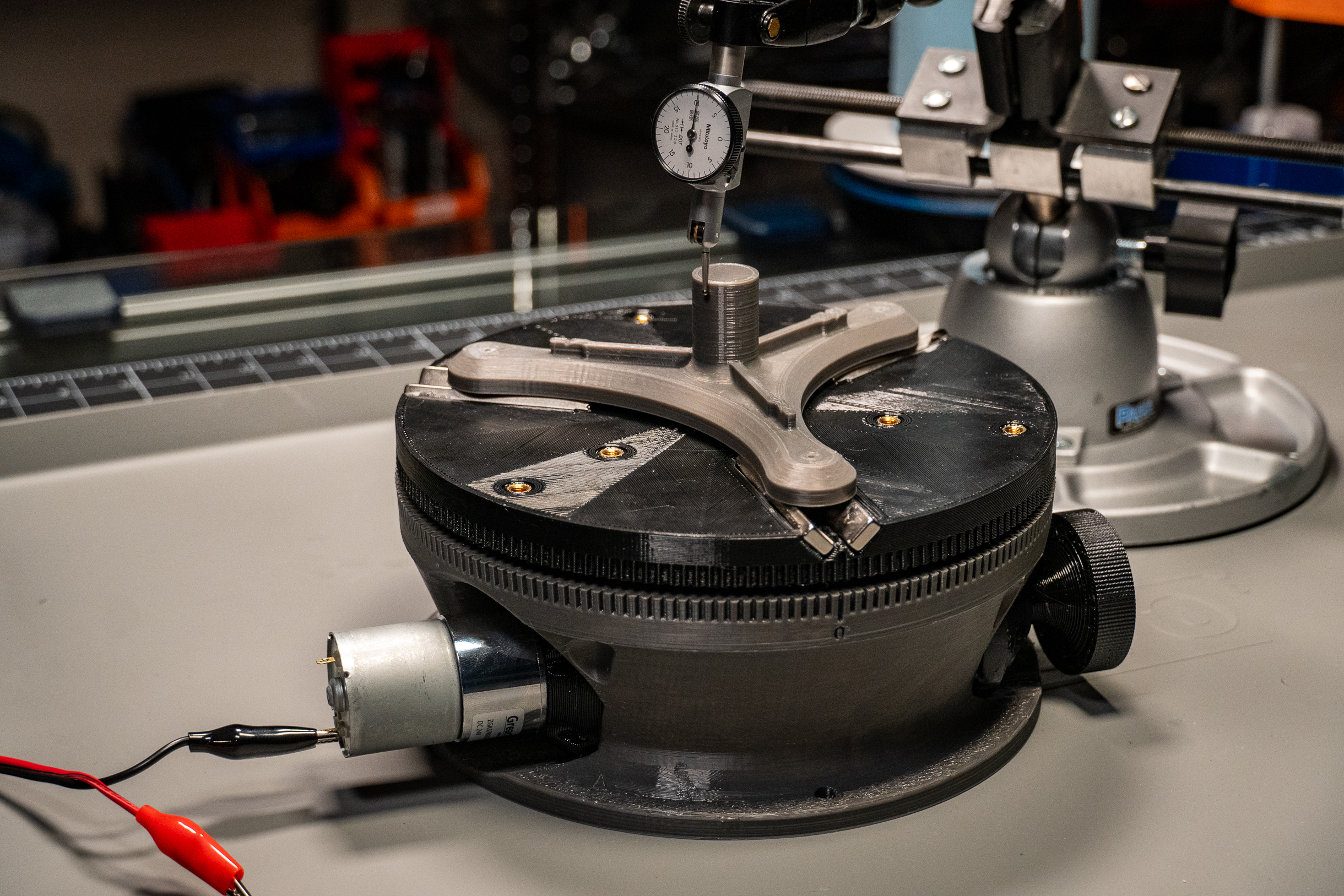
On top of the Table is the kinematic mount, formed by bar magnets set at 45 degrees from the table surface (so a 90 deg V.) If you haven't come across this style of interface before, you can find general info if you give a Google to "Maxwell clamp" or "kinematic coupler." I included a very similar coupler on my passive rotary / overkill papertowel holder build , as well as a great many of projects in my day job over the years...they're just tops :) hopefully seeing the repeatability numbers down below will start bringing you around to sharing my fondness for 'em.
One thing I decided to add that my machining rotary is missing is a power feed! In addition to the hand wheel for manually driving the table, a DC motor can be coupled to the other side of the drive mechanism. There also should be plenty of space to swap out this DC motor for a stepper, should I decide to down the line.
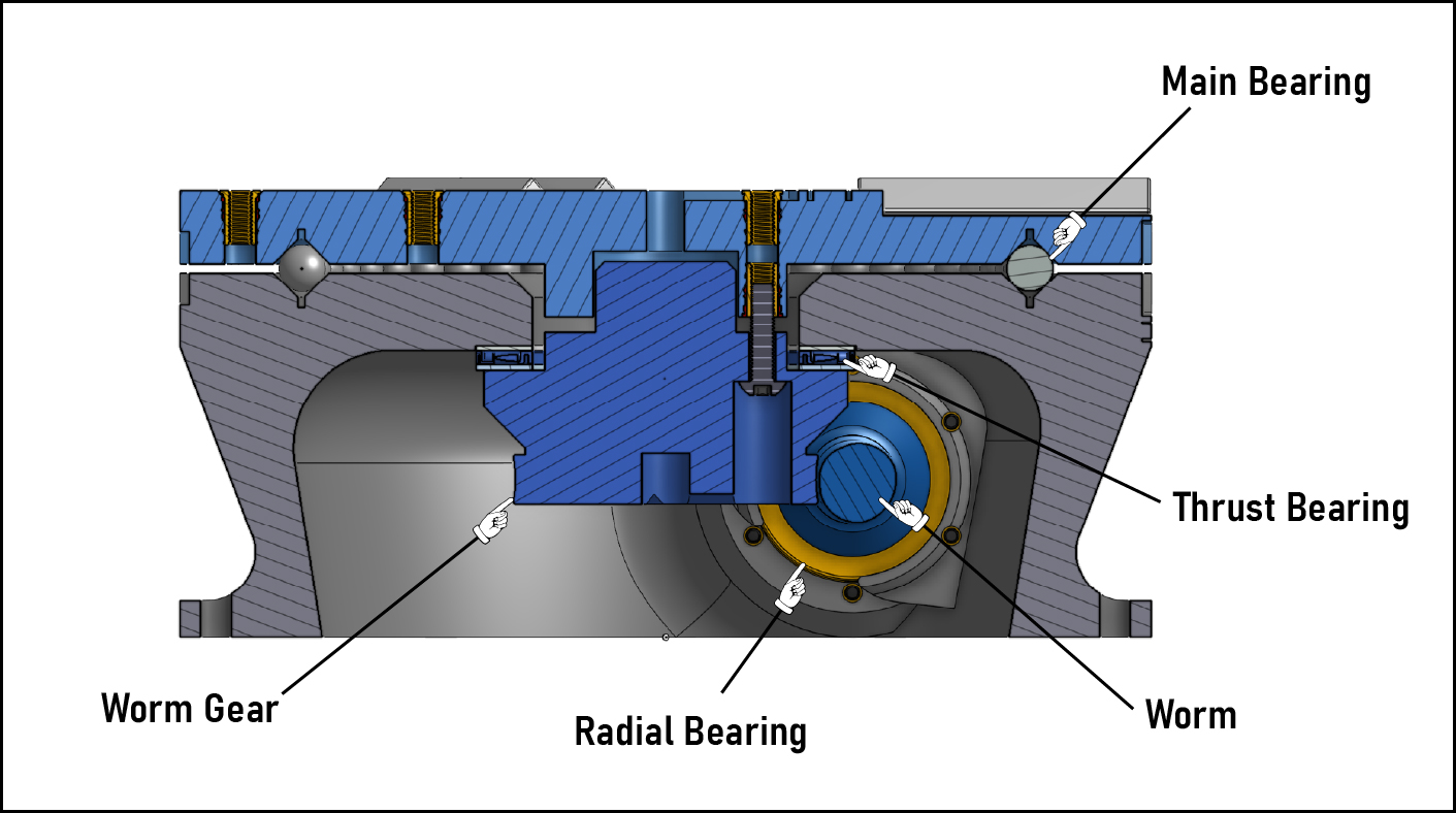
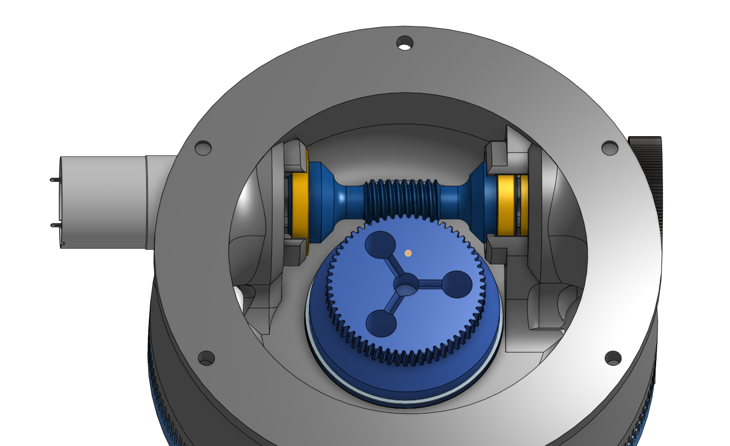
The Table is driven by a worm gear drive housed inside the base, as shown in the below image. The worm gear is integrated into Hub component, which attaches to the Table via three M5 fasteners. Sandwiched between the Hub and Base is a needle thrust bearing. This thrust bearing's counterpart is the main bearing that is integrated into the surfaces of the Base and Table. V-groove channels in the top of the Base and the bottom of the Table form the bearing races, and the rolling elements are 9.5mm steel balls (aka 3/8 inch slingshot ammo....hey, it's quite round and damn cheap).
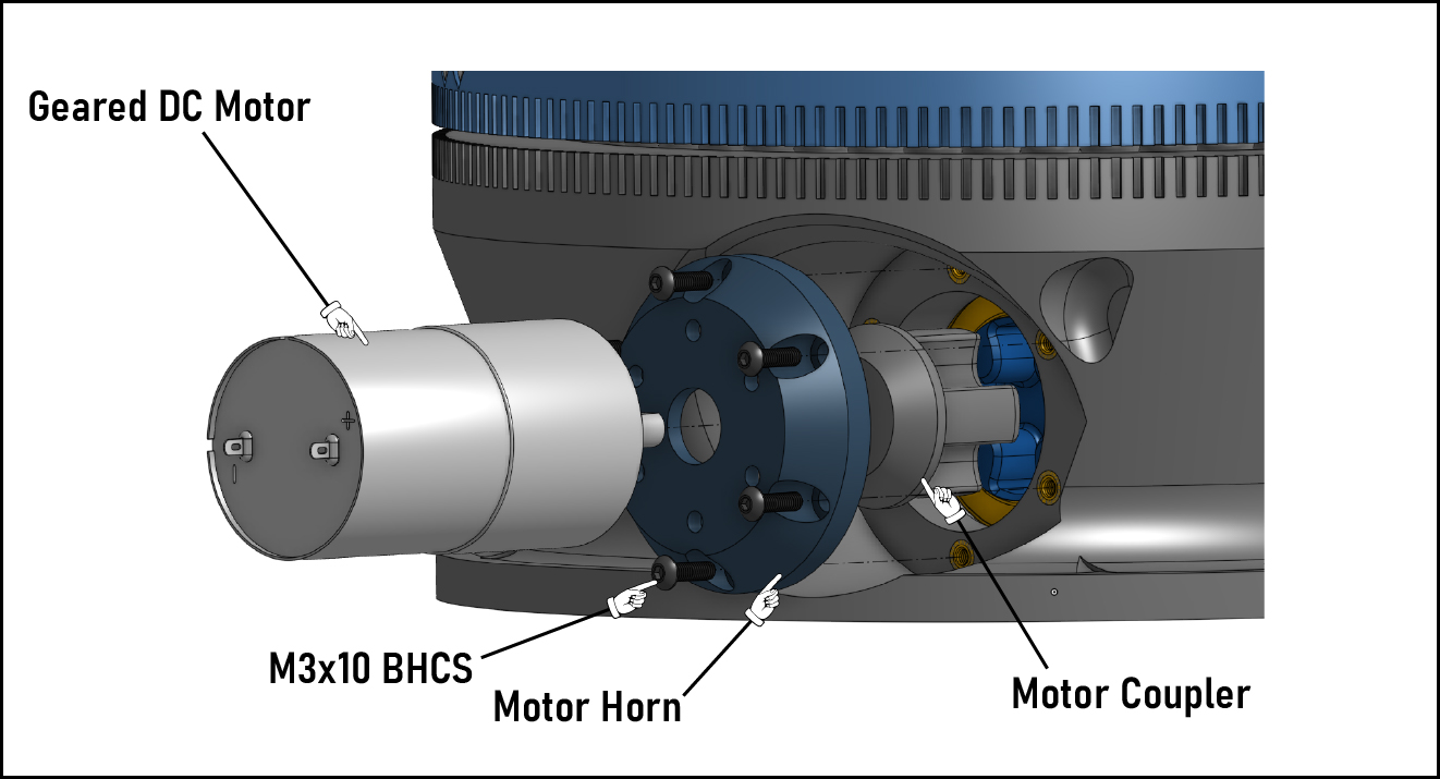
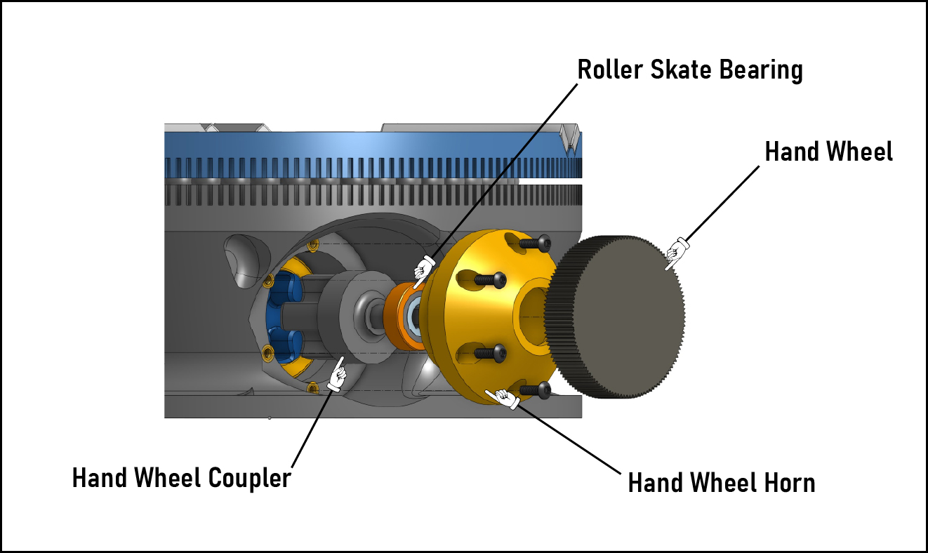
On the hand crank side of the table, a printed coupler sits inside the "hand wheel horn", held in place with a roller skate bearing (I used these. They're overkill for this, but they run really smooth.) The hand wheel presses onto the coupler with a light interference fit. It's really just intended as a close running fit, but with 3d printed parts it ends up being more like a bit of an interference fit.
On the power feed side is a similar printed coupler, but with a d-hub hole for engaging the motor shaft and no support bearing (the motor has a bushing that's serving the same purpose.) For a motor, I'm using one of these 24VDC, 150RPM motors. Something a little faster might be nice, but I might worry about the wear on the worm. Plus I don't really need this thing to be speed demon, so I don't have any plans to swap it.